Nous utilisons des cookies sur notre site web afin de vous fournir le meilleur service possible et d'améliorer encore notre site web. En cliquant sur le bouton "Accepter tout", vous acceptez l'utilisation de tous les cookies. Vous pouvez limiter les cookies utilisés en cliquant sur "Accepter la sélection". Vous trouverez de plus amples informations et une option pour révoquer votre sélection dans notre politique de confidentialité.
Ces cookies sont nécessaires pour la fonctionnalité de base. Cela vous permet de vous inscrire sur notre site web et notre forum ou de commander des produits avec notre boutique en ligne.
Avec ces cookies, nous collectons des données d'utilisation anonymisées pour notre site web. Par exemple, nous pouvons voir quel contenu est intéressant pour nos visiteurs et quelles résolutions sont utilisées. Nous utilisons ces informations pour optimiser notre site web et vous offrir la meilleure expérience utilisateur possible.
plus
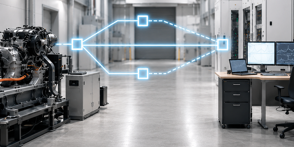
In modern automotive test environments – ranging from end-of-line testing to complex system tests – engineers often face the challenge of bridging significant distances between electronic control units (ECUs), test gantries, and measurement equipment. While this was feasible in many applications using traditional CAN networks, the introduction of CAN FD – despite enabling higher data rates – involves faster clocking, which significantly reduces the maximum transmission distance. Without appropriate technical measures, this leads to communication disruptions, erroneous messages, and system instability.
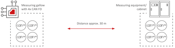
Figure 1: Problem statement – measurement equipment and DUT are spatially separated.
In an automotive test environment, electronic control units (ECUs) are connected to test bench automation and measurement equipment via a measurement gantry. In the scenario considered here, the gantry incorporates four CAN-FD channels, typically operated with an arbitration rate of at least 500 kbit/s and a flexible data rate (FD) of 2,000 kbit/s. However, there are also applications utilizing an arbitration rate of 1,000 kbit/s and flexible data rates of up to 5,000 kbit/s. The distance between the measurement gantry and the measurement equipment cabinet often exceeds 10 meters. Additionally, the measurement environment is subject to electromagnetic interference (EMI) from sources such as inverters, electric motors, or variable frequency drives. Without appropriate countermeasures, these distances can cause signal distortion, attenuation, or reflections on the CAN bus, potentially leading to disturbances, sporadic errors, or even system downtime. Signal quality on the CAN bus is frequently not measured, even during system acceptance testing; consequently, no data regarding the signal-to-noise ratio is available. It is therefore always advisable to measure signal quality and document the results for future comparison.
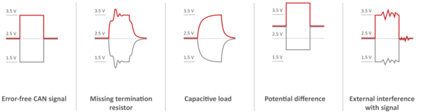
Figure 2: Signal fault patterns in CAN signal transmission over longer distances.
The challenge, therefore, lies in transmitting these CAN-FD connections over the entire distance with low latency – without compromising signal quality or performance, while ensuring secure galvanic isolation and high availability during testing. HMS Networks has developed five mature solutions that make it possible to operate the CAN bus over significantly longer distances.
The first option is based on the CANnector L, a multifunctional automotive gateway that offers integrated range extension in addition to standard bus connectivity. One CANnector L unit is placed at each end of the test setup – one at the measurement gantry and the other on the test bench automation or measurement technology side. While DIN-rail mounting in a control cabinet is possible, the devices are also suitable for mobile applications. Each CANnector L supports up to four CAN FD channels, allowing four channels to be transmitted across the entire configuration via a low-loss Ethernet connection. Galvanic isolation from the CAN bus minimizes interference, while additional functions such as data logging, residual bus simulation, and analysis options are simultaneously available. Users can configure additional filters and load DBC/ARXML data directly onto the devices, enabling flexible data streams to and from the automation system. It is also possible to distribute the data stream – or a portion of it – to additional devices, allowing calibration and diagnostic engineers to connect their tools without disrupting the overall system.
Relocating residual bus simulation to the devices at the measurement gantry enables real-time simulation (including MATLAB/Simulink) directly at the ECU, making it independent of the specific automation solution being used. Ultimately, the entire system and application must be evaluated in terms of data rate, number of buses, system characteristics, operating environment, and expandability.
For requirements involving higher computing performance, up to eight CAN FD channels, or other bus systems such as FlexRay, LIN, or Automotive Ethernet, the HMS Mobilizer product series can also be used.
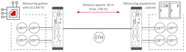
Figure 3: Illustration of Approach 1 – Bridging the distance and connecting the DUT to the measurement equipment using two CANnector devices.
The second solution utilizes the CAN@net NT420 or the PCAN-Ethernet Gateway FD DR featuring a compact design developed specifically for Ethernet-to-CAN bridging. Two of these devices are deployed on each side of the measurement gantry to implement the complete test setup. As with the CANnector L, data transmission relies on Ethernet tunneling – using either TCP/IP or UDP – ensuring transparent communication between endpoints with minimal latency. This solution is highly cost-effective and is particularly well-suited for permanently installed test environments where the number of channels is precisely defined and no advanced functional modules are required.
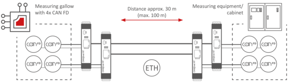
Figure 4: Illustration of Approach 2 – bridging the distance using four CAN@net NT devices.
The third variant combines the strengths of both previous approaches in a hybrid architecture. A high-performance CANnector L is used on the master side; it establishes the connection to the test system while simultaneously providing additional functions such as residual bus simulation or logging. On the other side, multiple CAN@net NT420 devices serve as slaves to distribute signals via Ethernet and bridge the physical distance. In a typical configuration, this setup comprises one CANnector L and several CAN@net NT420 units. This solution is particularly well-suited for large test benches where data must be distributed to various locations – for instance, to connect to measurement equipment, the control room, or diagnostic systems.
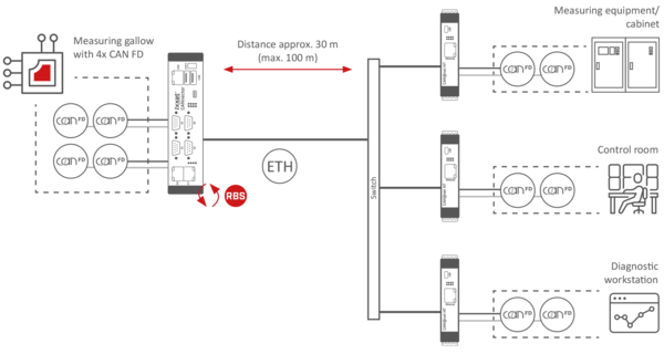
Figure 5: Illustration of Approach 3 – bridging distance via a hybrid architecture, suitable for connecting multiple remote measurement stations and control systems to the device under test.
The fourth solution approach is also based on a combination of the CANnector L and CAN@net NT420, but differs in terms of role allocation and the area of application.
Data from multiple identical devices under test (DUTs) is assigned an ID offset by the CAN@net gateways – an offset defined individually for each DUT. This allows the data to be transmitted jointly over a single channel, as each message can be uniquely assigned to a specific DUT. Configuration is handled via ACT, a user-friendly, free engineering configuration tool that also supports DBC and ARXML files.
A CANnector unit, equipped with a large number of CAN and CAN FD interfaces, is used in the control cabinet. It splits the data stream received via Ethernet and outputs the data – separated by DUT based on the ID offset – via its CAN or CAN FD channels. This enables the various CAN or CAN FD interfaces to be connected to the measurement equipment separately for each DUT.
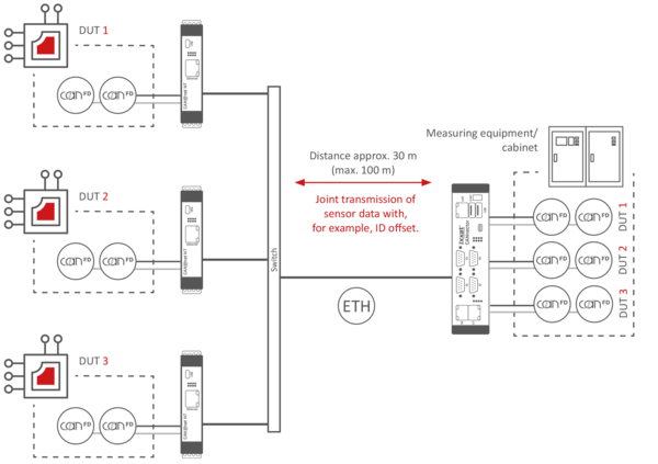
Figure 6: Illustration of Approach 4 – bridging the distance using a hybrid architecture to connect multiple identical test objects to a central measurement hardware unit. An ID offset via CAN@net enables transmission over a shared channel as well as the unambiguous assignment of data within the measurement system.
As a final option, HMS offers a low-budget, single-channel CAN FD solution. Two CAN@net basic devices are connected via UDP, enabling bidirectional data exchange. Particularly in scenarios using a dedicated Ethernet network, the downsides of UDP-based communication are generally acceptable. UDP offers the advantage of significantly lower protocol overhead compared to TCP/IP. This results in very low latency – averaging 0.3 ms (300 ns) – and jitter of less than 0.2 ms (200 ns), though these figures naturally depend on the overall system, bus load, and other factors.
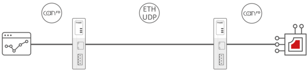
Figure 7: Illustration of Approach 5 – Low-budget CAN FD solution consisting of two CAN@net basic devices connected via UDP.
| Criterion | Solution 1 CANnector L | Solution 2 CAN@net NT420 | Solution 3 Hybrid (CANnector + CAN@net) | Solution 4 Extended hybrid structure (CANnector + CAN@net) | Solution 5 CAN@net basic |
|---|---|---|---|---|---|
Structure | Two identical CANnector L units, symmetrical installation at both ends | Two CAN@net NT420 units per side, pure gateway function | DUT side with CANnector L, opposite side with multiple CAN@net NT420 units – data distribution to multiple endpoints | DUT side with multiple CAN@net NT420 units for data aggregation, measurement side with CANnector for data splitting | One CAN@net basic per side |
Flexibility | Very high: Logging, residual bus simulation, and analysis possible on both sides | Low to medium: Focus on pure CAN frame transmission | High on the DUT side, compact setup on the opposite side | Compact on the DUT side, high on the opposite side | Low to medium: Focus on CAN frame transmission |
Costs | High (maximum features) | Low to medium (cost-optimized) | Medium (features on one side, cost optimization on the other) | Medium (features on one side, cost optimization on the other) | Very low |
Depending on the test environment, budget, and functional requirements, HMS Networks offers tailored solutions for extending the range of CAN/CAN FD buses. From the fully featured CANnector L and the compact CAN@net NT420 to hybrid architectures, these solutions ensure system stability, minimal latency, and a test setup that is both flexible and future-proof. In doing so, HMS Networks positions itself as a capable partner for engineers requiring a reliable, high-performance infrastructure for automotive testing environments.
 English
 Deutsch
 Français
 Chinois 中文
 Coréen


