We use cookies on our website to provide you with the best possible service and to further improve our website. By clicking the "Accept All" button, you agree to the use of all cookies. You can limit the cookies used by clicking on "Accept selection". Further information and an option to revoke your selection can be found in our privacy policy.
These cookies are necessary for basic functionality. This allows you to register on our website and forum or order products with our online shop.
With these cookies, we collect anonymized usage data for our website. For example, we can see which content is interesting for our visitors and which resolutions are used. We use the information to optimize our website to provide you with the best possible user experience.
show more
→ Go directly to the PCAN-Repeater DR or PCAN-Ethernet Gateway DR
Electromagnetic compatibility (EMC) testing requires reliable communication with electronic systems while ensuring that the test environment remains free from electromagnetic interference. When multiple Battery Management Systems (BMS) and lithium battery packs must be monitored simultaneously, maintaining uninterrupted CAN communication becomes particularly challenging. To address these requirements, PEAK-System France developed a communication architecture based on the PCAN-Repeater DR, PCAN-Ethernet Gateway DR, and PCAN-Explorer 7. This study presents the customer’s application, explains the communication setup, and shows how fiber optic transmission enables reliable CAN communication during EMC testing.
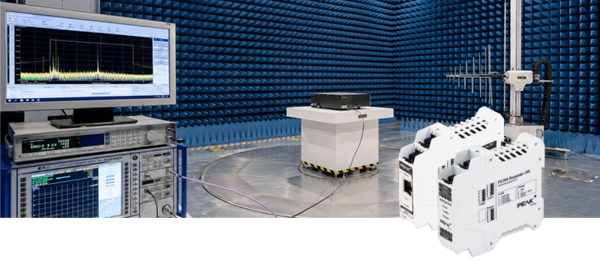
Emitec conducted electromagnetic compatibility (EMC) testing to validate multiple Battery Management Systems (BMS) and lithium battery packs simultaneously. Each BMS and battery pack communicated over its own dedicated CAN bus, resulting in a total of 12 independent CAN networks. Throughout the tests, the operator, located outside the anechoic EMC chamber, needed to monitor, analyze, and communicate with all battery packs and BMS units in real time.
The project presented two key technical challenges: First, no copper cabling could be routed between the inside and outside of the chamber, as metallic cables would interfere with EMC measurements and compromise test accuracy. Second, because each battery pack and BMS operated on a different electrical ground, galvanic isolation was required to prevent ground loops between the CAN networks.
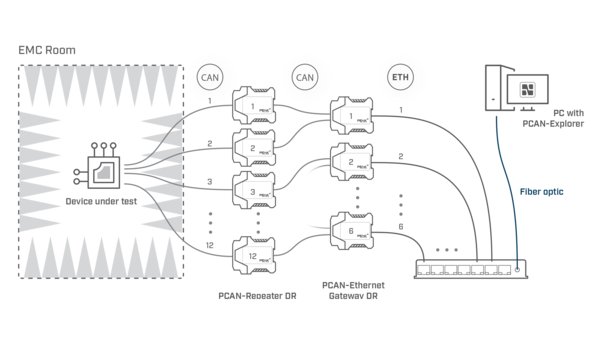
PEAK France designed a three-step communication architecture. A PCAN-Repeater DR was installed between each battery pack/BMS and the rest of the network to provide galvanic isolation, ensuring that all 12 CAN networks remained electrically independent. Each isolated CAN network was then connected to a PCAN-Ethernet Gateway DR, which encapsulated CAN frames into IP packets. As each gateway manages two CAN networks, six PCAN-Ethernet Gateway DR units were sufficient for the 12 CAN networks.
The Ethernet gateways were connected to a router using a fiber optic link that passed through the wall of the EMC chamber without affecting the tests. Outside the chamber, a second fiber optic router connected the network to the operator’s PC.
On the operator’s PC, the PEAK Virtual Gateway Driver reconstructed the 12 CAN networks. PCAN-Explorer 7 was then used to monitor and analyze CAN communication in real time. When required, firmware could also be reflashed using the integrated UDS/ISO-TP API within software developed specifically for the customer.
The solution enabled the operator to monitor and control 12 CAN networks in real time from outside the EMC chamber without interfering with EMC measurements. The architecture proved to be reliable, scalable, and reproducible for other EMC test benches.
 English
 Deutsch
 Français
 Chinese 中文
 Korean


